The VoIP Lounge

Icon

Incessant ramblings of a Unified Communications enthusiast with sporadic moments of sensibility.

Ways to Populate the CUCM Enterprise Directory with External Contacts

Basically, the enterprise phone book addresses two simple business needs – you need to see who’s calling you and you need to find quickly any contact and call him.

In Cisco UC environment this works well for employees  phones – if every employee is registered in Active Directory, you can find him on Cisco IP phone or Cisco Jabber and his name will be shown during the incoming call to you.

But what if you need your enterprise directory to contain not only employees, but also clients, partners and other external contacts? Or maybe your correct employees info is stored in 3rd party HR software, but not in AD?

There are several ways to populate the Cisco Unified Communications Manager corporate directory with contacts stored in 3rd party database.

  1. If you use Cisco Jabber you can use the Enhanced Directory Integration (EDI). This allows you to configure Cisco Jabber to search the contacts in any LDAP-based contact source. This contact source must be specified in Cisco Jabber config file (jabber-config.xml) and applied to all Jabber instances through TFTP server. So if you’re able to export all external contacts to some LDAP source and then maintain it up-to-date, you can use it as the search base for Cisco Jabber.
  2. If your CUCM version is 10 you can use the ECC (External Call Control) feature and CURRI (Cisco Unified Route Rules XML Interface) API. This approach supported in Cisco UCM 10.0 allows you to modify the caller name in telephony signaling on-the-fly. Aurus, one of the Cisco Solutions Partners offers the free CUCM External Caller ID web-application (with the source code) that connects to SQL DB to extract the contact name based on his phone number and set it as caller name using Cisco ECC and CURRI. Going this way you’ll be able to see, for example, the name of the client who is calling you. But you won’t be able to find the client on the IP phone or Cisco Jabber.
  3. If you’re open for the 3rd party solutions, consider applications provided by Cisco Solution Partners. Most of them provide the “Enterprise directory” XML-service for Cisco IP phones. Few vendors also provide the global phonebook for Cisco Jabber as well. With commercial app you’ll be able to import the contacts from any enterprise database, manage the synchronization schedule, setup the field mapping, use the phone numbers normalization feature and much more.

The post is provided by Aurus, Cisco Solution Partner developing software solutions for Cisco Collaboration and Contact Centers.

Aurus PhoneUP bundle, designed for Cisco Unified Communications Manager provide the full-featured enterprise directory for CUCM with Cisco IP phone and Cisco Jabber support.

Filed under: CUCM, , , ,

Upgrading CUCM to provide support for new IP phones

Hello everyone! It’s been quite some time since I’ve posted anything here. It has mostly been due to my incredibly tough schedule. I have yet to update the previous post about configuring a basic AA service on Unity Connection. I have the material ready in my head, but I wanted to get my hands on some screenshots to explain the process better. Basically, it will happen whenever I am able to gather all the screenshots.

Moving on to the topic of interest, this article will focus on provisioning support on Cisco Unified Communications Manager (CUCM) for IP phones that are not natively supported on your production system. In my example, I am trying to provide support for 7841 IP phones on CUCM version 8.6.2.

There are a several ways of finding out if your version of CUCM has built-in support for the phone model you would like to register. The easiest way to find out is to log into the web interface and navigate to Device -> Phones. Once on this page, click on “Add New”, which will take us to the page where we would normally add a new phone. Under the device type drop down menu, if the phone model does not exist, it means that the phone is not currently supported and a “device pack” will need to be installed on CUCM.

To successfully register an IP phone with CUCM, we will need to install a “device pack”. I am not certain if all device packs contain the firmware files, so I have included options to download and install these as well. This information can be verified by going through the release notes for the relevant release notes. Both the device pack and reloease notes can be downloaded through Cisco’s website under the Support -> Downloads section. (Note: A CCO ID with a valid service contract is required to obtain these files). To find out the what files need to be downloaded, we will need to first refer to the ‘Release Notes’ for the IP Phone model to find out the name of the device pack file. For the firmware files, we will need to download the file for the IP phone we are looking to support. Also, please ensure that this file is particular to the CUCM version you are running.

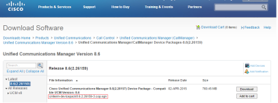
The screenshots below show the page where these files can be downloaded for our example upgrade:

Devpack


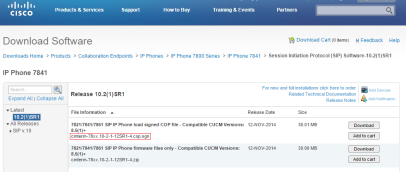
The page above displays the device pack file for our example. The image below shows the firmware files for the phones and CUCM version we are using in our example, that is, 7841.

Firmware

Before we begin uploading these files, I recommend taking a system backup through DRS and a VM snapshot if the server is running on a virtualized platform. Also, this process should be performed during a scheduled maintenance window.

Warning: I do not take responsibility for any system failure that may result from the procedures outlined in this document. This document is solely intended to provide general guidance to the reader, and it is the responsibility of the person performing this task, to ensure that all information particular to the upgrade is compatible with the production system. This includes for example, the correct CUCM version (Major and minor), IP phone firmware files, device pack file, and any other relevant system information.

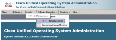
Once the backup is complete, we will need to log in through the OS Administration portal and navigate to Software Upgrades -> TFTP File Management, as shown in the screenshot below.

TFTP

Once on this page, click on the “Upload File” button, browse to the firmware files and upload

Here, we will upload the IP Phone firmware files to the TFTP server. (Note: These files will need to be uploaded separately to all TFTP servers in the cluster).

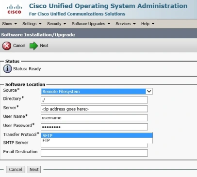
Once the TFTP files have been uploaded, we will need to apply the device pack file by navigating through the OS administration page, as follows: Software Upgrades -> Install/Upgrade. On this next page, we have the option to either install the device pack through a DVD/CD, or via the network. The network option is labeled “Remote destination”, which is what I have selected for our example. The screenshot below provides an example of how the necessary fields need to be filled out:

INST-UP

We have the choice to upload these files via FTP or SFTP. Free SFTP/FTP utilities are easily available for download on the internet. Before we proceed, I would like to mention that I had some trouble uploading the device pack from the root folder. Like any modern-age techie, I turned to the helpful technical forms on the internet and found that we will need to create another folder inside the root FTP/SFTP folder (give it any name) and place this file inside the new folder. Strangely, that seemed to work for me as well, so I thought it would be worth mentioning.

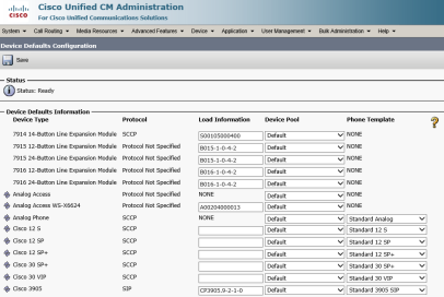
Before we proceed, I would like to add a word of caution; once the file has successfully completed, if the device pack contains the firmware files, it will most likely contain the firmware files for all other phones too. In addition, the “device defaults” page will be updated with the new firmware file names of all the IP phones. This means that for any new phone being added to the system, or an existing phones that are rebooted or restarted, will look for the new firmware files on the TFTP server. Use the following path to navigate to the device defaults page under CM administration: Device -> Device Settings -> Device Defaults

The device default page is shown in the image below:

DevDefaults

If these firmware files are not present (they have to be uploaded separately, as mentioned earlier in this post), the upgrade process will fail and the phone will boot up normally using the existing firmware file stored in its storage.  In a production environment, this could wreak havoc, so my suggestion would be to read through the device pack release notes and ensure if the firmware files for all phones are present inside the device pack.

If the firmware files are present in the device pack, we will have to upgrade the firmware files for all the IP phone models. However, this may not necessarily be a practical option in every scenario in which case, we will have to ensure that the firwmare filenames for all other IP phones that should not be affected by the upgrades, remain the same.

Unfortunately, there is no way at this time to retain the names, therefore, we will have to let the upgrade change the filesnames to the newer version, then go back to the device defaults page and reenter the old firmware file names from before running the upgrade. We could either take a screenshot of the device default page(s), or copy-paste the information on this page into a spreadsheet. I have not tried the latter and it may not work.

Once we hit the “Next” button, we may will be asked to ensure that the correct filename has been selected for upgrade. Clicking “Next” again may take us to a page where we are asked to ensure that the “MD5 hash authentication value” is correct for the file being uploaded. This can be verified by looking up the value in the release notes for the device pack. Proceeding to the next page will begin the installation.

Once the installation is complete we will need to perform a cluster-wide reboot, which can be done one server at a time. Again, I would advise caution when performing reboot of the servers because if the phones failover to a server that contains the newer firmware filenames, the phones will begin downloading the new files.

Once the servers have been restarted, the new IP phone model support will be available for registering with CUCM. I hope this article has been helpful to the reader. Please feel free to provide your feedback.

Filed under: CUCM, Technical, , , , , , , , , ,

CUCM Dial Plan for Pakistan

During my first CUCM implementation, I was completely lost as to where I should start creating a dial plan for Pakistan because all the documentation and books that I had read were targeted towards the North American numbering plan. This is understandable since most or all Cisco publication originated in North America. In any case, I was requested by a reader to share a dial plan for Pakistan, so I thought it would be a good idea to post that information here so that it may be helpful to others as well.

Please bear in mind that Pakistan uses a variable-length dial-plan, which may make it necessary to include a large number of route patterns, all of which I could not possibly include in this post. However, where possible, I have tried to define a general pattern that may have a considerable post-dial delay associated. This delay can be reduced in CUCM by tweaking the T.302 timer under System -> Service Parameters -> CallManager.

In my example, I have made the following assumptions:

–          The code to access an outside line is ‘9’
–          A Line/Device approach is being followed
–          The city for which the dial plan is being defined, uses 8 digit dialing.

First off, the Class of Restrictions (Calling privileges) will need to be defined by the administrator according to the client’s needs. However, I have found that most customers are happy to accept the administrator’s suggestions on the different privilege classes.

The Line CSSes will enforce the dialing restrictions. It will contain ‘Block’ partitions, which are partitions that contain Translation Patterns that will block access to the different route patterns. First, let us define the partitions and Translation Patterns that will block the route patterns. The administrator is free to choose labels of his/her choice. I have found the following configuration to be satisfactory for most clients:

Translation Pattern to Block Local Dialing (8-digits for Karachi and Lahore):

Pattern: 9.3XXXXXXX
Partition: PT-BLK-LOCAL
Check the: “Block this pattern” option

Translation Pattern to Block National Dialing:

Pattern: 9.0[^03]!
Partition: PT-BLK-NATIONAL
Check the: “Block this pattern” option

Translation Pattern to Block Mobile Dialing:

Pattern: 9.03XXXXXXXXX
Partition: PT-BLK-MOBILE
Check the: “Block this pattern” option

Translation Pattern to Block UANs:

Pattern: 9.111XXXXXX
Partition: PT-BLK-UAN
Check the: “Block this pattern” option

Translation Pattern to Block Toll-Free Numbers:

Pattern: 9.0800XXXXX
Partition: PT-BLK-TOLL-FREE
Check the: “Block this pattern” option

Translation Pattern to Block Premium Rate Numbers:

Pattern: 9.0900XXXXX
Partition: PT-BLK-PREMIUM
Check the: “Block this pattern” option

Translation Pattern to Block International Dialing:

Pattern: 9.00!
Partition: PT-BLK-INTERNATIONAL
Check the: “Block this pattern” option

Note: I have not defined blocking patterns for Service numbers since that would be too time consuming however, if desired, the administrator may do so. Service numbers are numbers such as Flight Inquiry, Sui Gas, etc.

Now let’s define the class of restrictions or the Line CSSes:

CSS-INTERNAL

PT-BLK-LOCAL, Partition to block Local Dialing
PT-BLK-NATIONAL, Partition to block National Dialing
PT-BLK-MOBILE, Partition to block Mobile Dialing
PT-BLK-UAN, Partition to block UANs
PT-BLK-TOLL-FREE, Partition to block Toll-Free numbers
PT-BLK-PREMIUM, Partition to block Premium Rate numbers
PT-BLK-INTERNATIONAL, Partition to block International Calling

CSS-LOCAL

PT-BLK-NATIONAL, Partition to block National Dialing
PT-BLK-MOBILE, Partition to block Mobile Dialing
PT-BLK-PREMIUM, Partition to block Premium Rate numbers
PT-BLK-INTERNATIONAL, Partition to block International Calling

CSS-NATIONAL

PT-BLK-MOBILE, Partition to block Mobile Dialing
PT-BLK-PREMIUM, Partition to block Premium Rate numbers
PT-BLK-INTERNATIONAL, Partition to block International Calling

CSS-MOBILE

PT-BLK-PREMIUM, Partition to block Premium Rate numbers
PT-BLK-INTERNATIONAL, Partition to block International Calling

CSS-INTERNATIONAL

PT-BLK-PREMIUM, Partition to block Premium Rate numbers

Note: Emergency numbers should not be placed in any partitions so that every extension has access to emergency dialing.

The Device CSS will allow access to all route patterns, and therefore, should contain the appropriate partitions as follows:

DEVICE-CSS (You may choose a label of your choice)

PT-INTERNAL: Partition for Internal extensions
PT-LOCAL, Partition for Local Numbers
PT-NATIONAL, Partition for National Numbers
PT-MOBILE, Partition for Mobile Numbers
PT-SERVICE-NUMBERS, Partition for Service Numbers
PT-UAN, Partition for UANs
PT-TOLL-FREE, Partition for Toll Free Numbers
PT-PREMIUM, Partition for Premium Numbers
PT-INTERNATIONAL, Partition for International Numbers

Finally, we will need to define the route patterns for all numbers:

Route Pattern for local dialing:

Pattern: 9.3XXXXXXX
Partition: PT-LOCAL
Provide outside dialtone: YES
DDI: Pre-dot

Note: For cities that use 7 digits or less, a route pattern with the appropriate number of digits may be defined.

Route Pattern for National dialing:

Pattern: 9.0[^03]!
Partition: PT-NATIONAL
Provide outside dialtone: YES
DDI: Pre-dot

Route Pattern for National dialing with #:

Pattern: 9.0[^03]!#
Partition: PT-NATIONAL
Provide outside dialtone: YES
DDI: Pre-dot + Trailing #

Route Pattern for Mobile dialing:

Pattern: 9.03XXXXXXXXX
Partition: PT-MOBILE
Provide outside dialtone: YES
DDI: Pre-dot
Route Pattern for local dialing:

Route Pattern for International dialing:

Pattern: 9.00!
Partition: PT-INTERNATIONAL
Provide outside dialtone: YES
DDI: Pre-dot

Route Pattern for International dialing with #:

Pattern: 9.00!#
Partition: PT-INTERNATIONAL
Provide outside dialtone: YES
DDI: Pre-dot + Trailing #

Route Pattern for UAN Numbers:

Pattern: 9.111XXXXXX
Partition: PT-UAN
Provide outside dialtone: YES
DDI: Pre-dot

Route Pattern for Toll-Free Numbers:

Pattern: 9.0800XXXXX
Partition: PT-TOLL-FREE
Provide outside dialtone: YES
DDI: Pre-dot

Route Pattern for Toll-Free Numbers:

Pattern: 9.0900XXXXX
Partition: PT-PREMIUM
Provide outside dialtone: YES
DDI: Pre-dot

Route Pattern for Police Department:

Pattern: 9.15
Partition: <None>
Provide outside dialtone: YES
DDI: Pre-dot

Route Pattern for Police Department without outside access code:

Pattern: 15
Partition: <None>
Provide outside dialtone: NO
DDI: None

Route Pattern for Punjab Rescue:

Pattern: 9.1122
Partition: <None>
Provide outside dialtone: YES
DDI: Pre-dot

Route Pattern for Punjab Rescue without outside access code:

Pattern: 1122
Partition: <None>
Provide outside dialtone: NO
DDI: None

Route Pattern for Flight Inquiry:

Pattern: 9.114
Partition: PT-SERVICE-NUMBERS
Provide outside dialtone: YES
DDI: Pre-dot

Route Pattern for SUI Gas:

Pattern: 9.119
Partition: PT-SERVICE-NUMBERS
Provide outside dialtone: YES
DDI: Pre-dot

Route Pattern for PTCL Inquiry number:

Pattern: 9.1217
Partition: PT-SERVICE-NUMBERS
Provide outside dialtone: YES
DDI: Pre-dot

Route Pattern for PTCL Complaint number:

Pattern: 9.1218
Partition: PT-SERVICE-NUMBERS
Provide outside dialtone: YES
DDI: Pre-dot

General Route Pattern for Service Numbers:

Pattern: 9.1!
Partition: PT-SERVICE-NUMBERS
Provide outside dialtone: YES
DDI: Pre-dot

General Route Pattern for Service Numbers with #:

Pattern: 9.1!#
Partition: PT-SERVICE-NUMBERS
Provide outside dialtone: YES
DDI: Pre-dot + Trailing #

I hope this information was helpful to the reader.

Filed under: CUCM, Technical, , , , , , , , ,

Configuring Extension Mobility in CUCM 6.x – 8.x

I was going to do a detailed post on configuring Extension Mobility in CUCM, but then I came across a blog that already has a comprehensive, step-by-step post on the subject so I thought I would simply link to it. To configure Extension Mobility in CUCM 6.x – 8.x, follow this link. Good luck!

Filed under: CUCM, , ,

Cisco Unified Communications Manager Software Compatibility Matrix

The software compatibility matrix for all version of CUCM are available here. This can prove to be a very useful document during deployment since it addresses almost all types of software/firmware compatibilities.

Filed under: CUCM, Technical, ,

Call Park vs Directed Call Park

There are times when you are on the phone with someone when you suddenly realize that your two office pals are hanging on to every word of your conversation which makes it rather difficult to pursue a private conversation. At that moment you wish you had a way to transfer the call into some mysterious data cloud whence you could retrieve it at another phone of your choice. Well, the call park feature can do just that for you. All you have to do is hit the “park” key on your IP phone and voila! The call is dispatched or “parked” in a virtual spot on Cisco Unified Communications Manager (CUCM). Your phone will display the extension that can be dialed at any phone to retrieve the parked call bearing in mind that call park extensions, as with any other DNs can be assigned partitions – which implies that the appropriate Call Search Space would be required to access this extension whether the call is being parked at or being retrieved from the call park extension.

As an example, a range of unused extensions 500x (where x is a wildcard that may represent digits 0-9) can be assigned for call park. When a user wants to park the call, they simply press the “Park” softkey on their phone and the call gets transferred to the first available call park slot. The user on the other end of the call is placed on hold. Assuming all slots are available, the call will be transferred to extension 5000. To retrieve the call, the user may go to any phone and dial “5000” and the call will be immediately connected to the other end that was placed on hold.

A similar feature called “Directed Call Park” is also available on CUCM where the user can hit the “Transfer” key and specify (dial) a directed call park extension that has been configured by the administrator. This is different from call park where the call was automatically parked at an administrator-configured extension. Of course this isn’t the only difference – the extension is configured with two parts: The first part is the directed call park slot extension and the second part is the retrieval code or retrieval “prefix.” The retrieval prefix is ‘prefixed’ to the call park slot in order to retrieve the call. Without the retrieval prefix the call cannot be retrieved and therefore gives the user some measure of authentication when “parking” their call.

This feature is particularly  helpful in retail stores where a receptionist can take a call and “park” it for a particular users. The receptionist can then announce on the PA system, a message along the lines of “Mr. Simpson – please retrieve your call on extension 01”. Assuming that the retrieval prefix is set to 51, Mr. Simpson will dial 51-01 to retrieve the call. Cisco recommends that either one of the two features be configured at once, but not both. If both features need to be configured, it is highly recommended that the extensions do not overlap.

Hope that was helpful!

Filed under: CUCM, Technical, , , ,

Configuring Intercom in CUCM 6.x – 8.x

An intercom line is one of those ‘must-have’ functions that must be available on every PBX. Fortunately, CUCM does have this function, but on the other hand, the documentation explaining how the feature works and its related configuration is not so accurate. Anyway, here’s my attempt at configuring this simple, but very handy feature in CUCM 6.x – 8.x:

Before I begin, I want to mention that an intercom line is represented by a Directory Number (DN) as is the case with any dial-able entity. Now that we have that out of the way, the first thing one needs to understand is how an intercom line works. Simply put, a user (generally a manager) presses an intercom line button on their phone and it dials the intercom line on other user’s (generally an assistant) phone and the call is auto-answered at this user’s end. However, the second user can only listen to the first user’s voice, but their own phone is muted by default. The general idea behind the intercom line is for a manager to speed-dial into a second user’s phone and have it auto-answer at the receiving end in muted mode. This allows the manager to deliver a quick, one-way audio message to the assistant. If the assistant wishes to respond back to the manager, they can hit the intercom line button on their phone and initiate a two-way conversation;  just like a normal phone call.

The intercom line is an additional line on an IP phone that is configured to reach another intercom line on another IP phone. Intercom lines are configured with “Intercom Partitions” and “Intercom Calling Search Spaces” and therefore only intercom lines can reach other intercom lines. When a user presses the intercom line on their IP phone, they can manually (or configure it to automatically) dial the corresponding intercom line on the other IP phone. Generally, a Manager will have an intercom line to their Assistant’s phone, which will be the scenario for our example.

The setup:

A manager would like to have an intercom line to their assistant such that they would simply need to press the line button and have the assistant’s phone auto-answer (in muted mode). The intercom should not work in reverse, that is, the assistant should not be able to speed-dial the manager’s intercom line.

The configuration:

– Create two ‘Intercom partitions’ for the Manager and the Assistant’s intercom DNs by navigating to Call Routing -> Intercom -> Intercom Route Partition. Title the partitions something along the lines of “PT-INTERCOM-MANAGER” and “PT-INTERCOM-ASSISTANT”.

– Create two ‘Intercom CSSs’ for the Manager and the Assistant’s intercom DNs by navigating to Call Routing -> Intercom -> Intercom Calling Search Space. Title the CSSs something along the lines of “CSS-INTERCOM-MANAGER” and “CSS-INTERCOM-ASSISTANT”. Configure the Manager CSS to contain the Assistant’s Intercom partition (PT-INTERCOM-ASSISTANT) so that the Manager’s Intercom CSS will having dialing access to the Assistant’s intercom DN. The Assistants Intercom CSS will also contain the Assistant’s intercom partition only because the CSS cannot be left empty.

You’re probably wondering why we need to set up a CSS for the assistant since they won’t need any dialing privileges on their intercom line, however, both intercom partition and intercom CSSs are mandatory configuration entities for any intercom line regardless of the requirement. Go figure!

– Create an ‘Intercom Directory Number’ for the manager’s phone by navigating to Call Routing -> Intercom -> Intercom Directory Number as show in Figure 1. We will configure 3000 as the Manager’s Intercom DN.

Figure 1 – Intercom Directory Number Configuration for Manager

– Create a second ‘Intercom Directory Number’ for the assistant’s phone as show in Figure 2. We will configure 3001 as the Manager’s Intercom DN.

Figure 2 – Intercom Directory Number Configuration for Assistant

– Add an intercom line to the Manager’s phone by navigating to Device -> Phone and then selecting the phone to which the intercom line will be added. Click on the “Modify Button Items” button as show in figure 3. A small window may pop-up that reads: “Unsaved Changes may be lost! Continue?”. Click on OK and the “Reorder Phone Button Configuration” window will pop-up.

Figure 3 – “Modify Button Items” under the Phone Configuration window

– Highlight the ‘Intercom [1] – Add a new intercom’ option under the “Unassigned Associated Items” box on the right side of the window and press the “<” button to move the intercom line into the left box (Associated Items). Rearrange this option and place it in the line position where it will appear on the phone as shown in Figures 4 and 5. Note: The number of options in the left box must correspond to the number of lines on the phone. Hence, one of the unused lines may have to be moved over into the right box before the intercom option can be moved here. If this hasn’t been done and the user attempts to add an intercom line to the left box, the following error will be received: “Must Remove An Item From Associated List Before This Operation is Allowed”.

Figure 4 – Reorder Phone Button Configuration window Step 1

Figure 5 – Reorder Phone Button Configuration window Step 2

– Click on “Save” and then “Close”.

– Under the second line (where the intercom was configured) will now read: “Intercom [1] – Add a new Intercom”. Click on this link and on the next page enter the DN (3000 in our example) in the ‘Intercom Directory Number’ field and hit “tab”. The remaining fields will be automatically pulled from the Intercom Directory Number settings configured earlier as illustrated in Figure 6.

– The following fields may be entered if desired (Shown in Figure 6):

Display (Internal Caller ID)

ASCII Display (Internal Caller ID)

Line Text Label

ASCII Line Text Label

Figure 6 – Intercom Directory Configuration Window

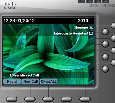
– The “Speed Dial” field will set the intercom to dial this number (3001 in our example) as soon as the Intercom line button on the IP phone is pressed. This is illustrated in Figures 7 and 8.

Figure 7 – Normal State

Figure 8 – After Pressing the “Intercom Line”

Please feel free to post any questions or comments. I hope this post was helpful!

Filed under: CUCM, Technical, Uncategorized, , , , , ,

Standard Local Route Groups Explained

At first glance, Standard Local Route Groups (or just Local Route Groups) seemed like a mystery to me, perhaps because I hadn’t seen it used in a real-life scenario and had only abstract notes and articles explaining its operation and advantages. I understood that it somehow eliminates the pairing between the gateway and the Route Pattern, thus creating a more flexible method of selecting a PSTN gateway.

Additionally, because it reduces the number of route patterns that need to be created per country (as long as the country’s dial plan is uniform), a huge amount of administrative overhead can be saved, especially for organizations with a large number of sites.

So, without further adieu, let me lay out my explanation of how Standard Local Route Groups (SLRGs) work and how they can result in significant flexibility in route selection and savings in administrative overhead.

Before I begin, I’d like to make it clear that SLRGs only apply to a centralized call-deployment.

Prior to the introduction to SLRGs, a dial plan for each site had to be created separately. This meant that each site required a set of Route Patterns, Route List(s) and Route Groups. For an organization with 10 sites, this would require us to configure:

–          Number of Route Patterns (let’s assume 10 patterns for our example) for each site multiplied by the number of sites (10 sites), which comes out to 100 Route Patterns

–          Number of Partitions for Route Patterns multiplied with the number of sites  (we will assume each Route Patterns is placed in a separate partition) multiplied by the number of sites, which comes out to 100 Partitions

–          10 Route Lists (1 for each site)

–          10 Route Groups (1 for each site).

I have illustrated the aforementioned explanation in figure 1 using 2 sites instead of 10 to save myself some time.

Now let’s take a look at how we can accomplish the same thing using SLRGs. As is evident from figure 2, we associate the Karachi Route Group for with the Karachi Device Pool and the Lahore Route Group with the Lahore Device Pool. These Device Pools will then be applied to the phones for their respective sites. Now, here is where the savings are evident – we will create a single set of Route Patterns (10 patterns) for the entire country!

The reason for the enormous reduction in the number of Route Patterns is that we no longer need to separate Route Patterns for each site using different Partitions and we will no longer need to create separate Partitions for each site since all sites will use a single set of Route Patterns.

Since the selection of the gateway will now depend upon the Route Group assigned to the device initiating the call, through the Device Pool (as mentioned before) instead of the fixed Route Pattern/Route List/Route Group association, all devices can use the same set of Route Patterns per country (as long as the dial plan for the country is consistent as mentioned before).

After the call path flows from the Route Pattern through the Route List and hits the Route Group, the SLRG (a dynamic entity) selects the Route Group and consequently the local gateway based on the Route Group association at the Device Pool level. This is further explained visually in figure 3.

Let us now take a look at how much work we (as the administrators) have saved ourselves:

–          Number of Route Patterns for each site multiplied by the number of sites (10 sites), which comes out to 10 Route Patterns => 100 – 10 = 90 less Route Patterns that need to be configured.

–          Number of Partitions for Route Patterns multiplied with the number of sites multiplied by the number of sites, which comes out to 10 Partitions => 100 – 10 = 90 less Partitions that need to be configured.

–          1 Standard Local Route Group => 10 – 1 = 9 less Local Route Groups that need to be configured.

–          10 Route Groups (1 for each site) = No savings here.

These administrative overhead savings are even more significant for a larger number for sites.

I hope my attempt at explaining the self-purported ‘mystical’ idea behind how SLRGs function was helpful to others.

Filed under: CUCM, Technical, Uncategorized, , , , ,

Cisco UCM Corporate Directory Issue: Host not found

While deploying CUCM BE 8.5.1 for a client, I came across an issue where, selecting the Corporate Directory option on the IP phones was displaying a “Host not found” error. After reading through a lot of forums and documentation, amidst the heaps of Cisco guides, I came across a document that contains a fix for the issue. There were several posts on various IT forums that seemed to suggest that the issue may be fixed by eliminating DNS reliance, so I tried both and I was able to resolve the issue! I am not certain which of the two solutions did the trick, but I would suggest doing both step-by-step, although since the issue has been documented by Cisco itself, I would put my money on their solution.

DNS reliance can be eliminated by replacing the CUCM hostname with the server’s IP address. This is done under the CUCM Administration page by navigating to System -> Server.

Cisco’s suggested fix is to do the following:

  • Remove the Secure URL entry for Directory URL under the Enterprise Parameters.
  • Make sure that the firewall settings are not blocking access.
  • Restart the Cisco Trust Verification Service.
  • If the show itl command displays the Verification of the ITL file failed. Error parsing the ITL File error message, regenerate the TVS certificate from the CUCM OS Administration Page. For information on regenerating the TVS certificate, refer to the Security section of the Cisco Unified Communications Operating System Administration Guide.

Source: Unified CallManager 5.x/6.x/7.x: Issues with Corporate Directory Lookup

Hope this helps!

Filed under: CUCM, Technical, Uncategorized, ,

Follow me on Twitter

Random Technical Imagery

Categories

Authors

Enter your email address to follow this blog and receive notifications of new posts by email.

Join 315 other subscribers
Follow The VoIP Lounge on WordPress.com

Did you know?

The SIP protocol does not carry the number 'type' information for calling number such as 'international' or 'subscriber' etc. Therefore, for incoming calls at the PSTN, the calling number needs to be manipulated at the gateway before the call is routed to the call agent over a SIP trunk.